2026-09-06 · phase 0 · status paper only — no change to the hardware
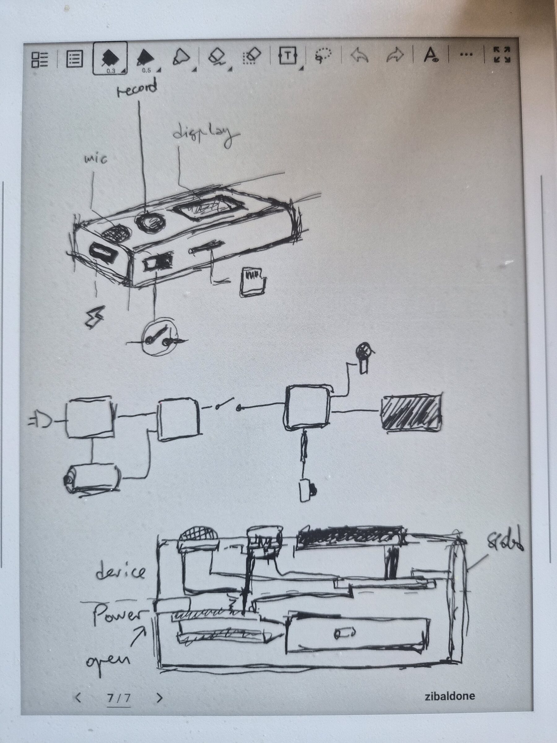
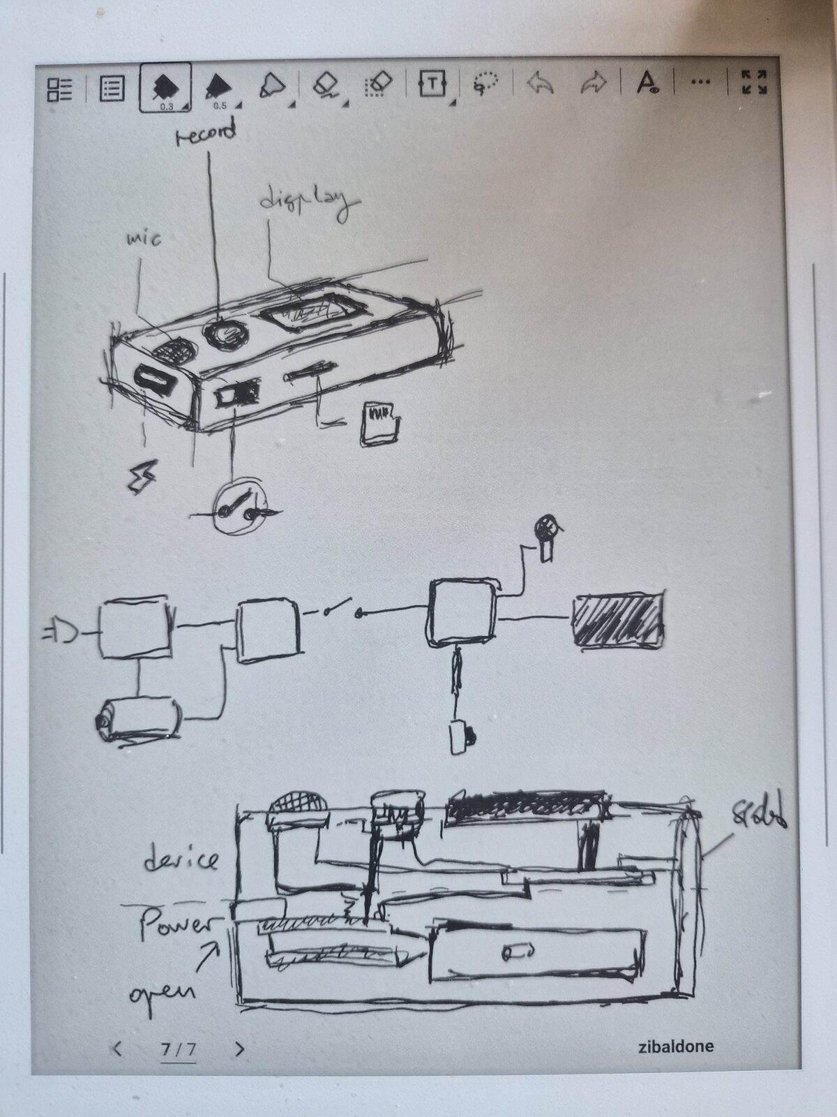
Sat down with the Supernote and drew the thing rather than describing it. Three passes on
one page: the outside, the wiring, and the inside.
Outside. A puck. Mic grille and the record button on the top face, display
next to them, and everything else pushed to one side edge — USB-C for charge, the microSD
slot, and the slide switch (drawn out in the callout, since it's the one control you operate
without looking).
Block diagram. USB-C → charger → cell → boost → switch → S3 → display, with
the mic branching off the S3 one way and the microSD the other. This is just the chain from
yesterday's bench wiring, on paper — no surprises, which is the point of drawing it.
Inside. A section through the case: board over the battery compartment,
mic port at the top, and an arrow for how the two halves come apart. The stack is taller than
I'd like — the boost module is the part making it so.
Next: OLED I2C lines, then the mic, then the first bench-test — unchanged.
2026-09-05 · phase 0 · status power rail feeds the S3; OLED powered; button on GPIO1
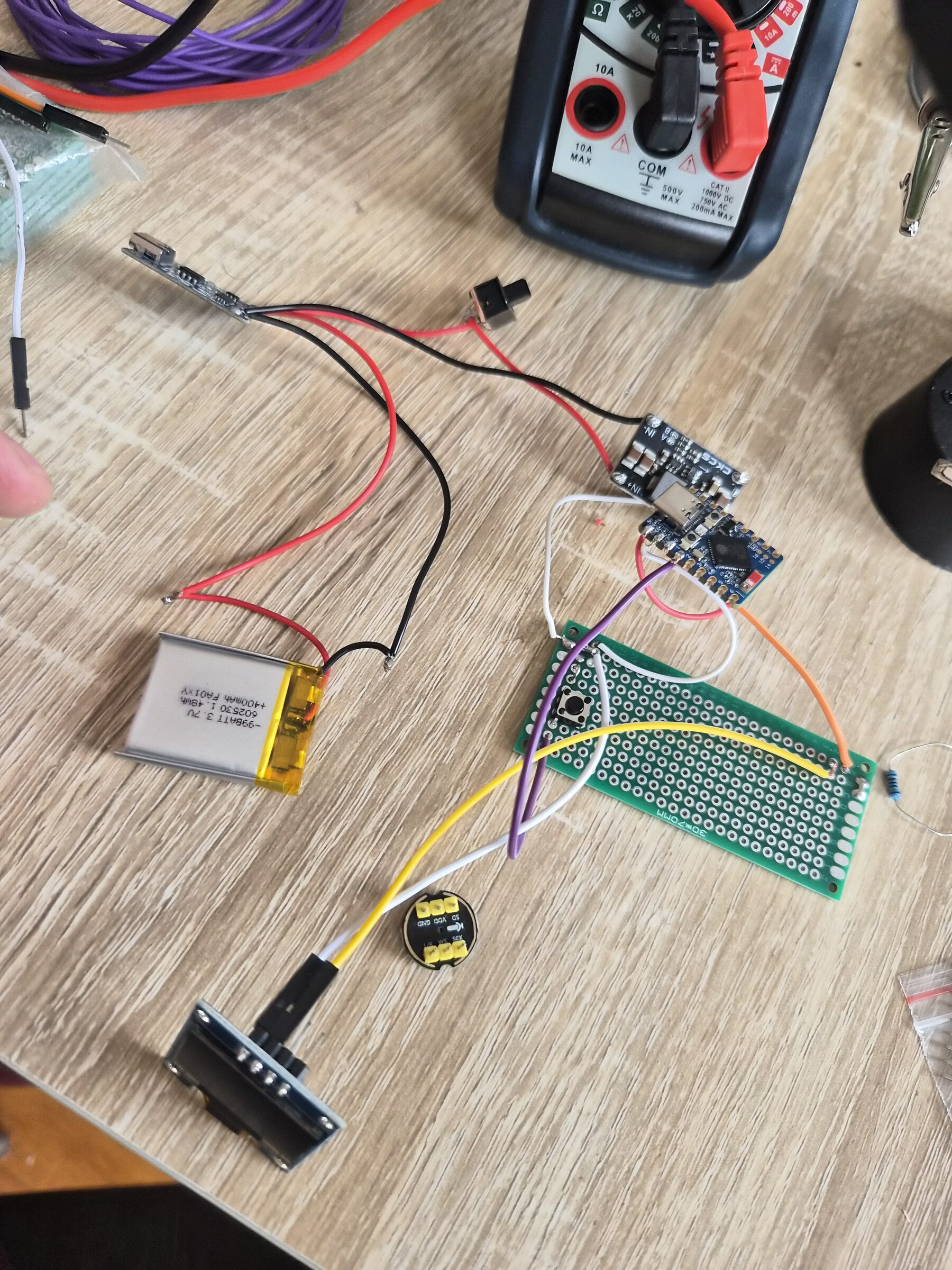
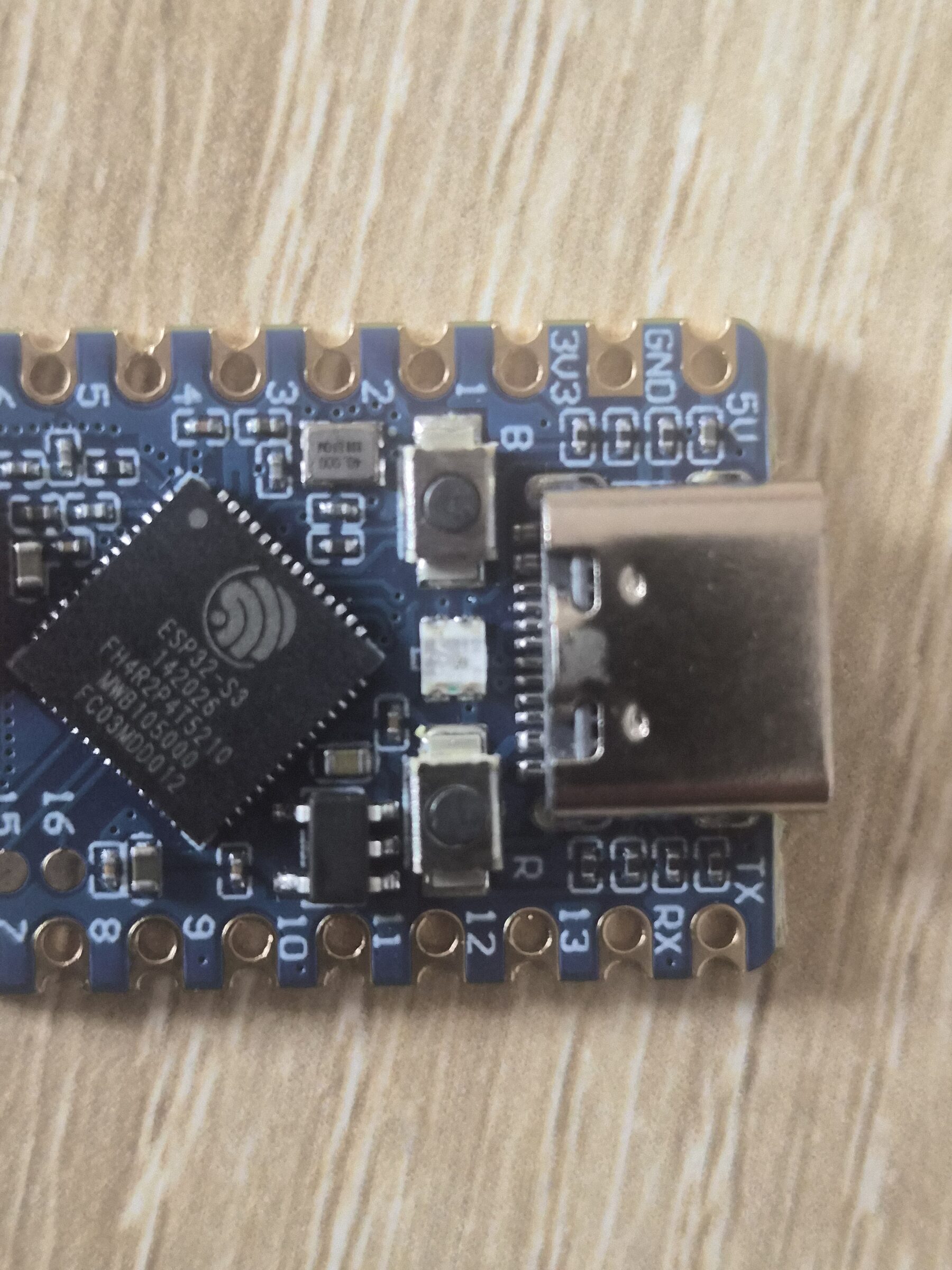
Added a 3.3V→5V boost converter between the TP4056 and the ESP32-S3-Zero. The TP4056's
output is just raw cell voltage (~3.0–4.2V), which is too low to feed the S3's 5V pin and
too high to safely feed 3V3 directly — the boost module resolves both. The slide switch
now sits on the positive line between the TP4056 and the booster, so it gates the whole
converter rather than just the board.
Grounds: booster GND runs to the S3 and to the OLED. The OLED's VCC comes off the S3's
3V3 pin (i.e. the S3's own regulator powers the screen, not the booster). OLED data lines
(SDA/SCL) aren't run yet.
Record button is in: microswitch between GND and GPIO1, not GPIO2 as
originally speced. GPIO1 is not a strapping pin on the S3, so it's a fine choice — docs
updated to match the hardware rather than the other way round.
Next: OLED I2C lines, then the mic, then the first bench-test.
2026-08-09 · phase 0 · status power chain soldered and verified working
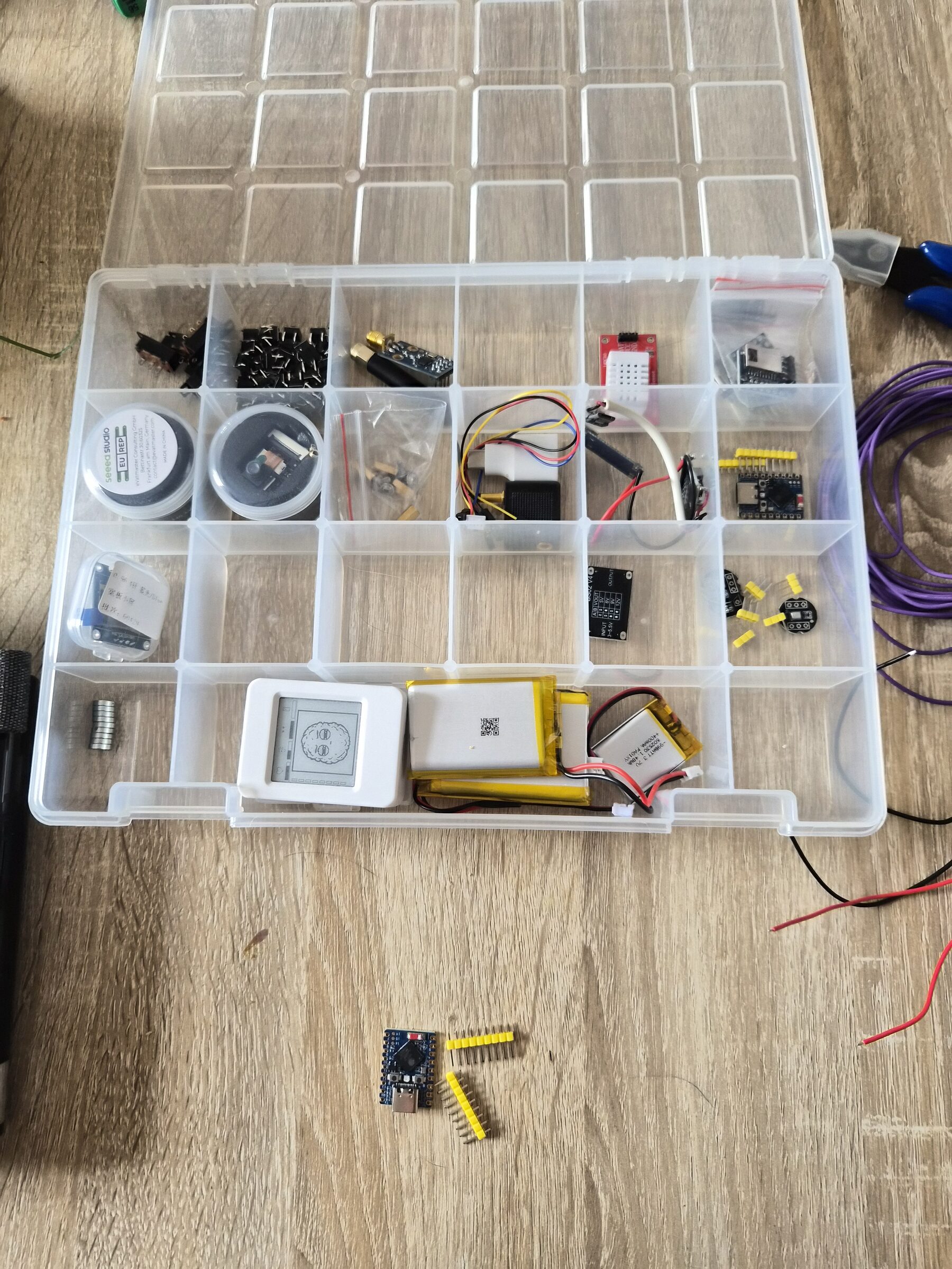
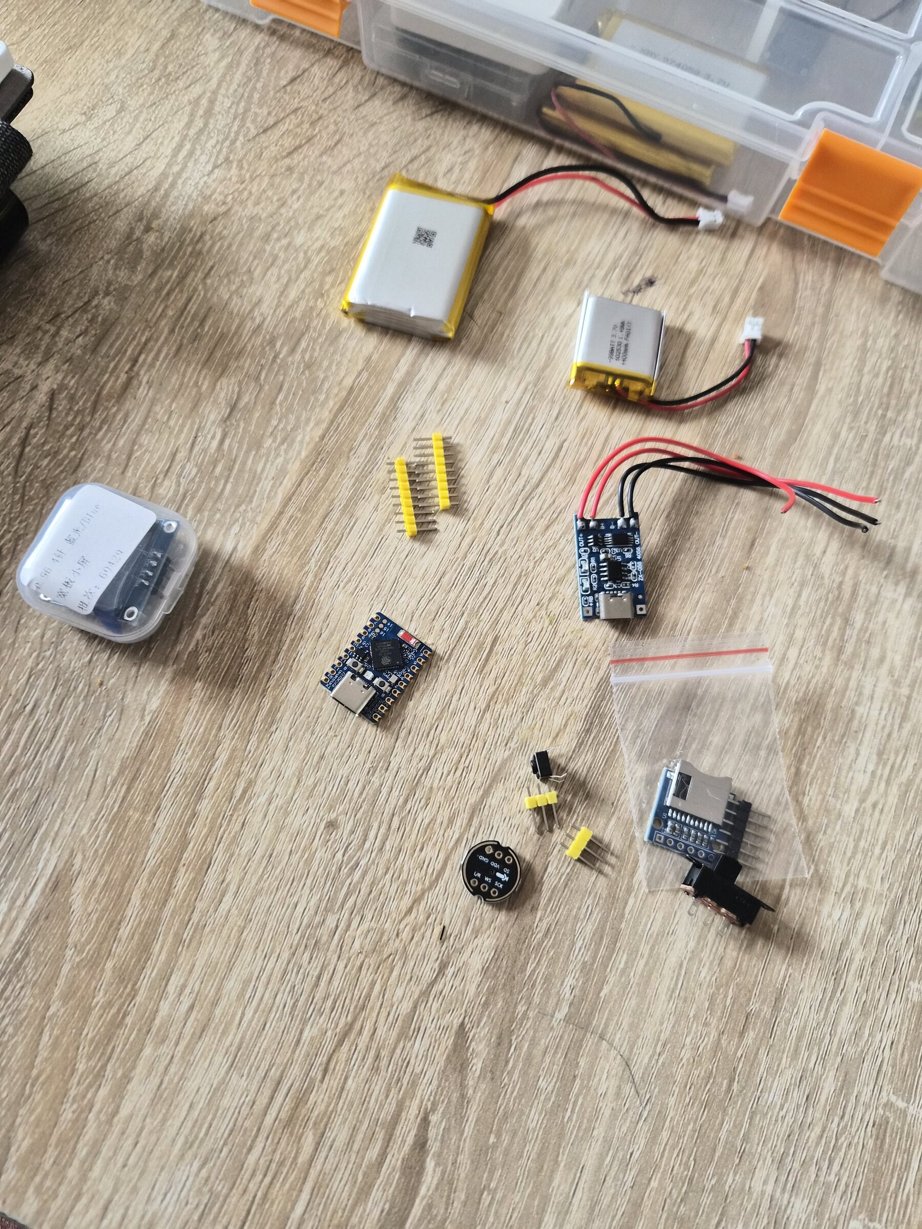
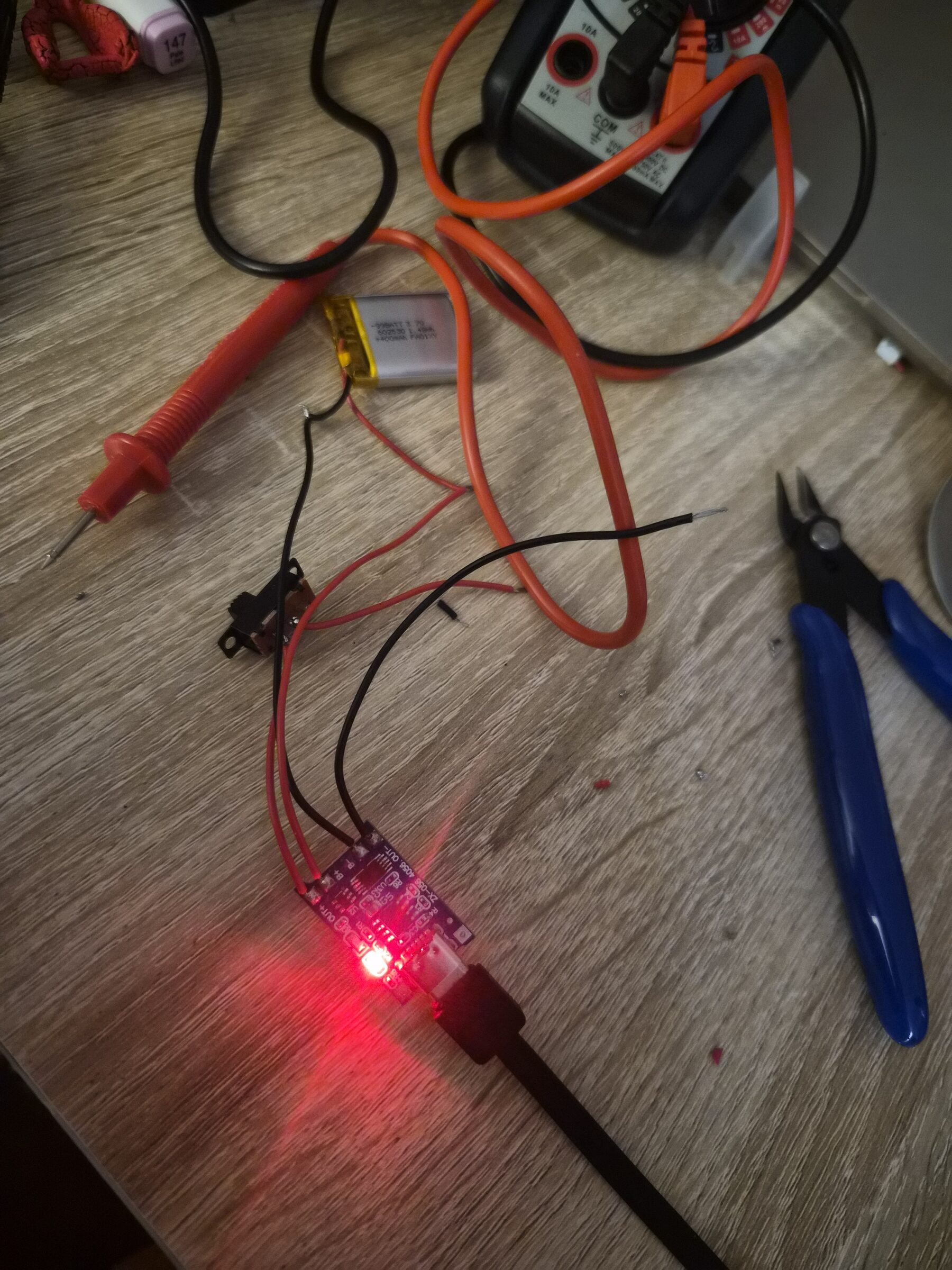
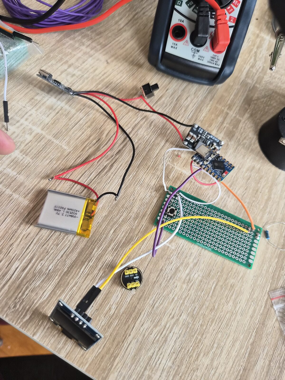
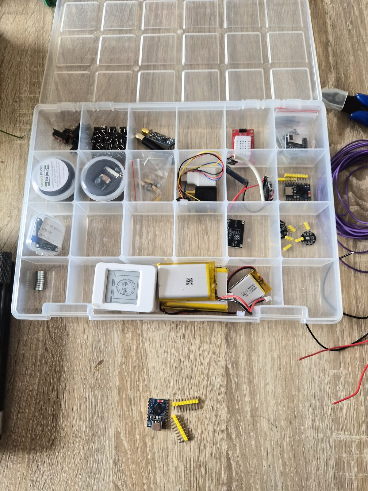
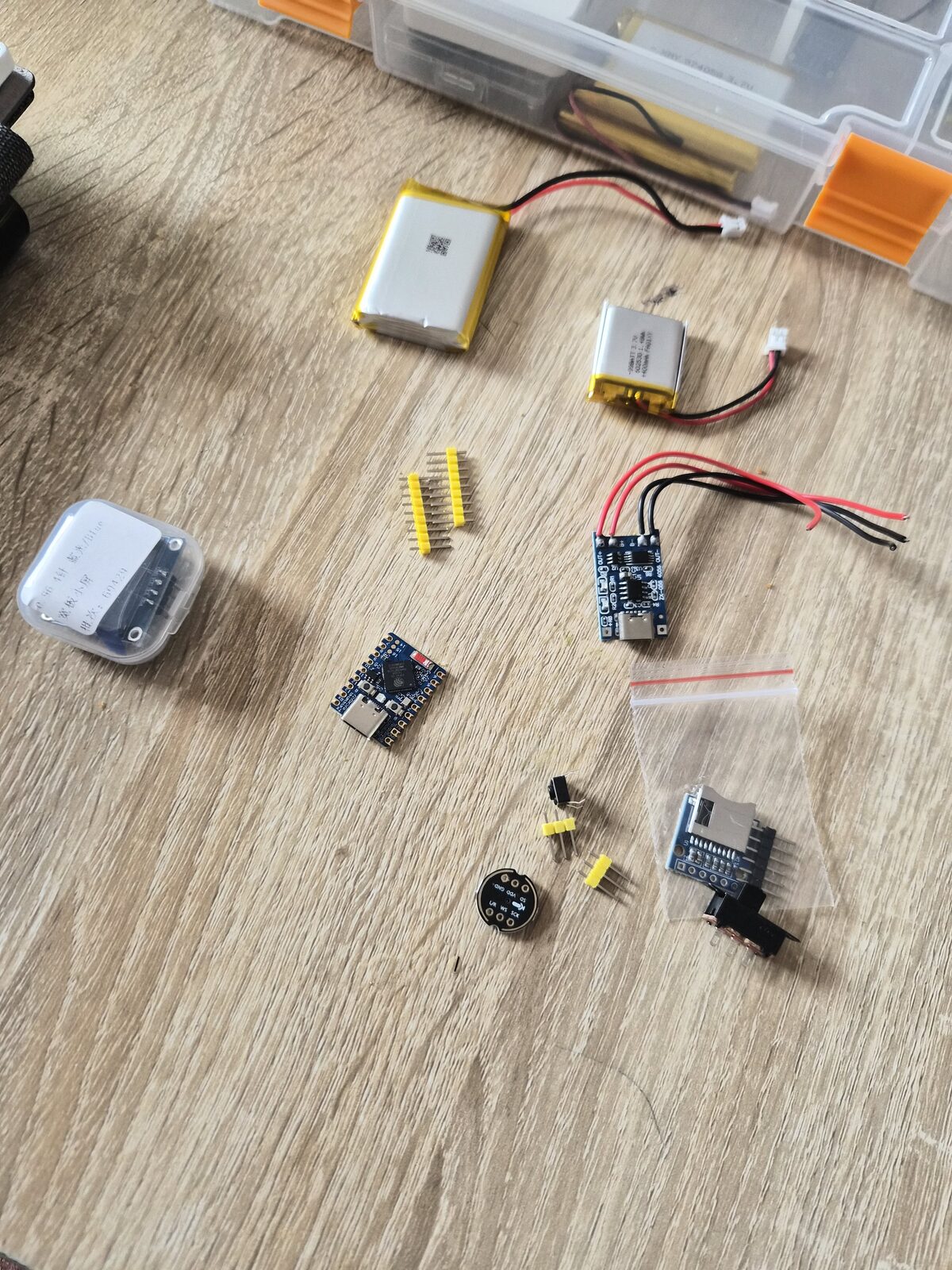
Checked the inventory and confirmed the whole BOM is accounted for, then roughly
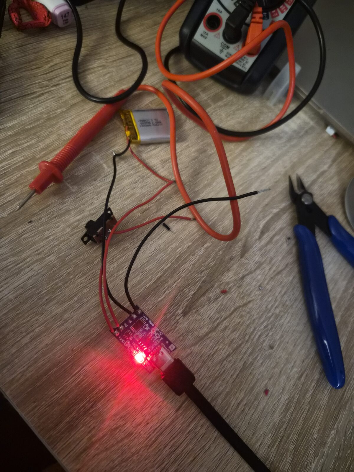
assembled the power chain — a quick bit of soldering done while supporting my son's
drawing session. Power chain works.
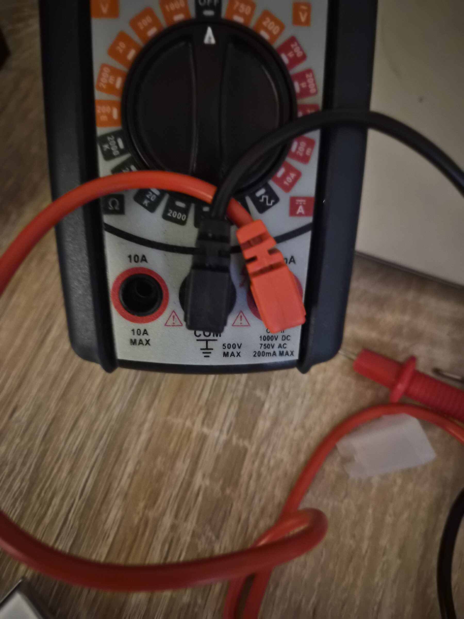
The fun part: today's work was so simple and straightforward that it got messy
when it didn't seem to work — I had no output power. After desoldering and resoldering 2–3
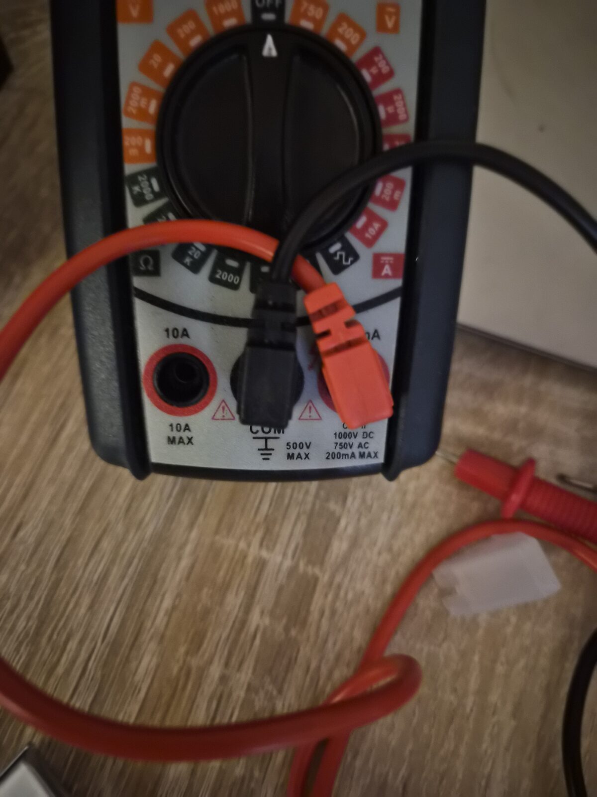
times, I realized one of the multimeter cables (the ground one) was slightly loose, pulled
out just enough to not measure. The power chain had been fine the whole time; the
measurement was the problem.
2026-08-08 · phase 0–1 · status docs/scaffolding only, no hardware work logged yet
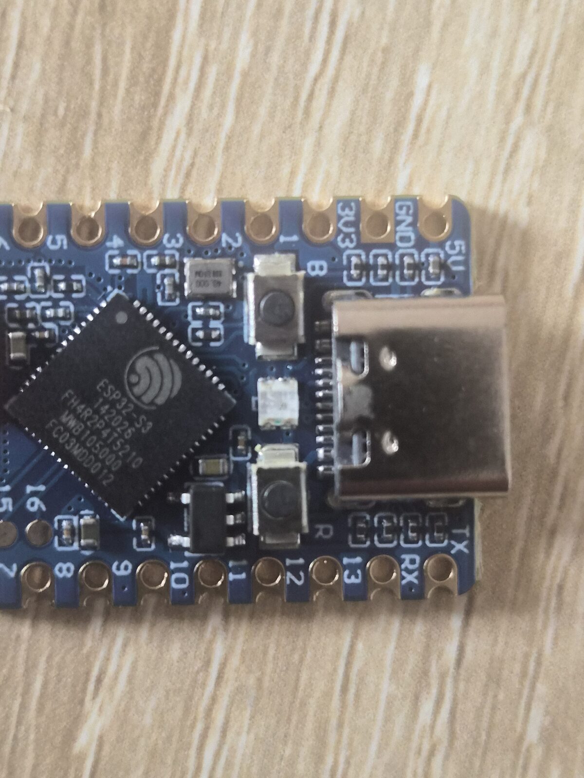
Set up the repo from the spec: firmware/android/hardware/docs scaffold, pinout, BOM,
roadmap, and agent docs. quantum-basics attached as a submodule. No soldering or
bench-testing done yet — puck parts are in hand except the microSD card and LiPo
(pending purchase). First hardware entry will land once headers are soldered and the
mic/OLED/button bench-test runs.